SO, I posted a quick "1st week using the Hemera" video on YouTube. Got a few responses thatchy wanted to see the actual prints, so here ya go.
** Note, Using the Hemera on a Semi large CoreXY frame (500mm cube structure)
--- Using a 0.8 Micro Swiss coated nozzle
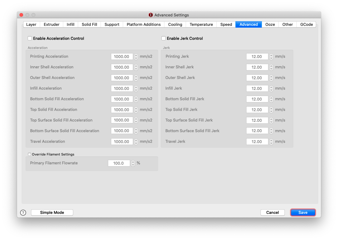
still tuning and setting up the slicing. I use Ideamaker so take what ya can from that. I'll show images of my slicer settings below-
A little PLA coat hanger and a TPU wire holder
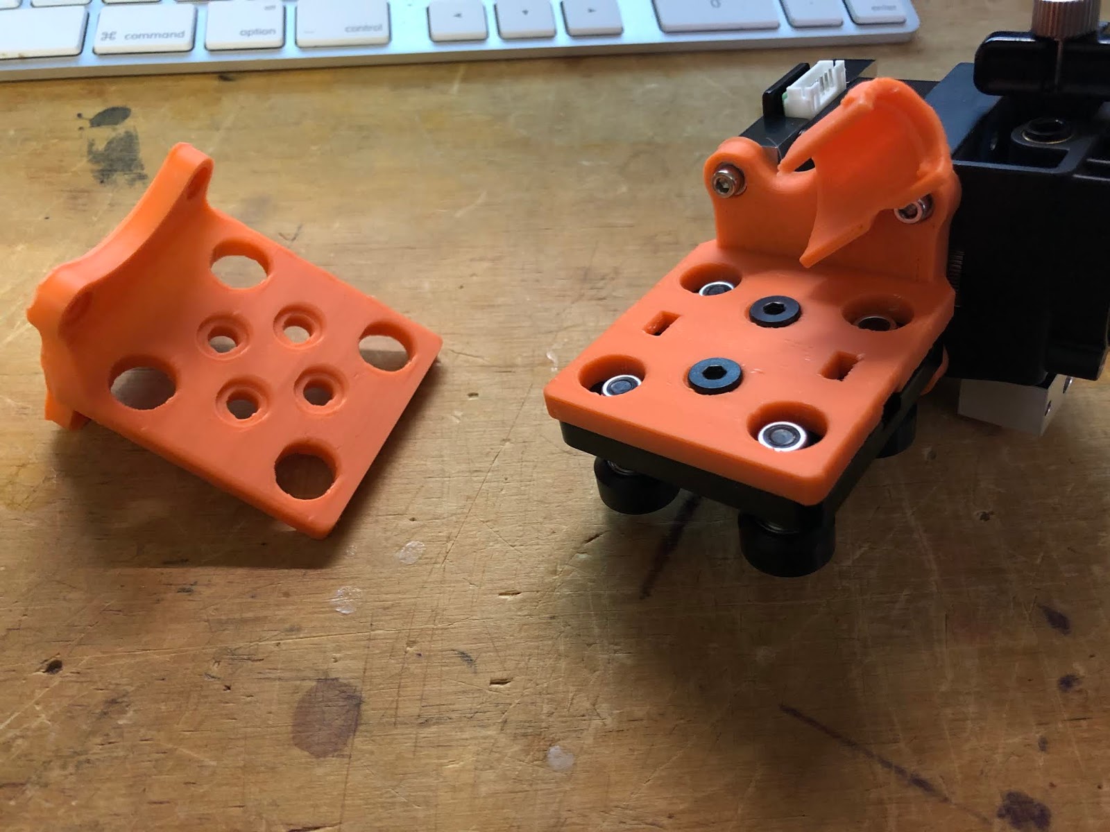
Hemera Mounts for the Frown King (Anet E12)
New Endstop (better alignment)- More TPU wire management parts
Big Mystery panel!
And here's the slicer settings, again these aren't perfect yet, but working generally OK. getting a tad of "hump" in some corners X/Y and still just a tad of stringing (but it is a 0.8 nozzle not a 0.4 so ..)
OK, here are the dimensions for the clip design I did in Fusion 360 and made a video about how to go about making your own. this is the base clip in a 1//2 section so you'll need to mirror it.
OK, this will be a basic flappy hawk assembly instructions. More for the 3D printed parts, stringing and weighting is kinda trial and error at this point.
First off, printing settings, these are just suggestions that have worked for me, experimentation is fun though! NO SUPPORT USED!!! If you have IdeaMaker or Simplify 3D you can place supports inside the body cavity if you want, but really not needed.
Wings - it's all 4's with a 0.2 layer height, 4 Shells, 4 top, 4 bottom, 40% infill. this makes the wings weight up a bit which is needed for balance
Body & Tail - 0.2 layer, 2 or 3 shells, 2 bottom, 3 top, 20% infill
Hanger, hooks(need 2) and pull(need 2 or maybe 3) - pretty much what ever you want and works well for your printer, 2 or 3 shells with 3 bottom/top layer as 20% infill seems decent for me.
**TEST AND FIT ALL MOVING PARTS BEFORE GLUING ANYTHING!**
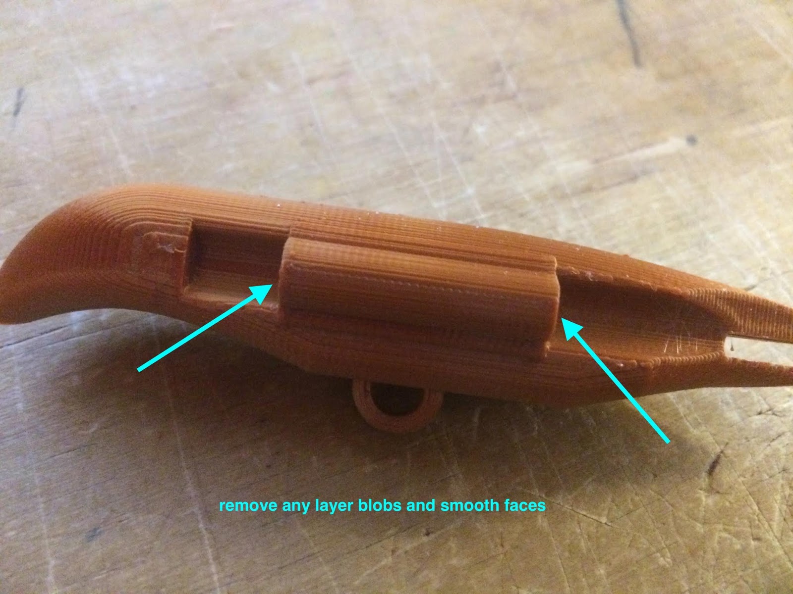
Once printed you'll likely need to do a little cleanup. The meeting faces between the wings and the body hinge needs to be smooth and clean of print boogers, strings and rough edges.
Clean up mating faces of hinge as best you can
After Cleaning up an faces, take a piece of standard PTFE tubing (4mm exterior by 1.75/2mm interior)
and cut a length just short of the hinge length in the body, and insert into the body hinge of each half.
Now Prep the holes in the wing, cut a scrap of filament (1.75) and use it to test and make sure it can slide in and through, but not so loose it'll just fall out. With the printing layers it should be a bit too hard to get in, I use another scrap piece of filament and mount in a drill, spinning at a very slow speed, use it to ream out the opening! Do both sides!
Now just place the wing in the body half, and slide the piece of filament from the rear through the wing and body to create the hinge. Slide it in till it just comes out the front, but not out so far it's beyond the indent in the body. You can snip off the excess at this point at the back, though I leave it a tad long still so I can grip it and remove if there is an issue down the road!
At this point go ahead and flop it around and make sure there isn't anything binding at the hinge on either wing!. If all is good, you can glue the body halves together. I take it all apart just because it's easier to handle that way. I apply glue on the front 2/3rds of the body, clamp it and use the tail slipped in to make sure it's all aligned. I only glue the front 2/3rds because we don't want to get glue on the tail. I WOULDN'T GLUE THE TAIL IN! as it's a lot easy to work on the wings and hinge later if you can pop that tail out!! The Tail is indented to align everything but should be tight enough to stay on its own.
If you took off the wings to glue the body together, pull the taill of, re install the wings and then slide the tail back in.
OK, that's it, you now have the main body built. Next is stringing it.
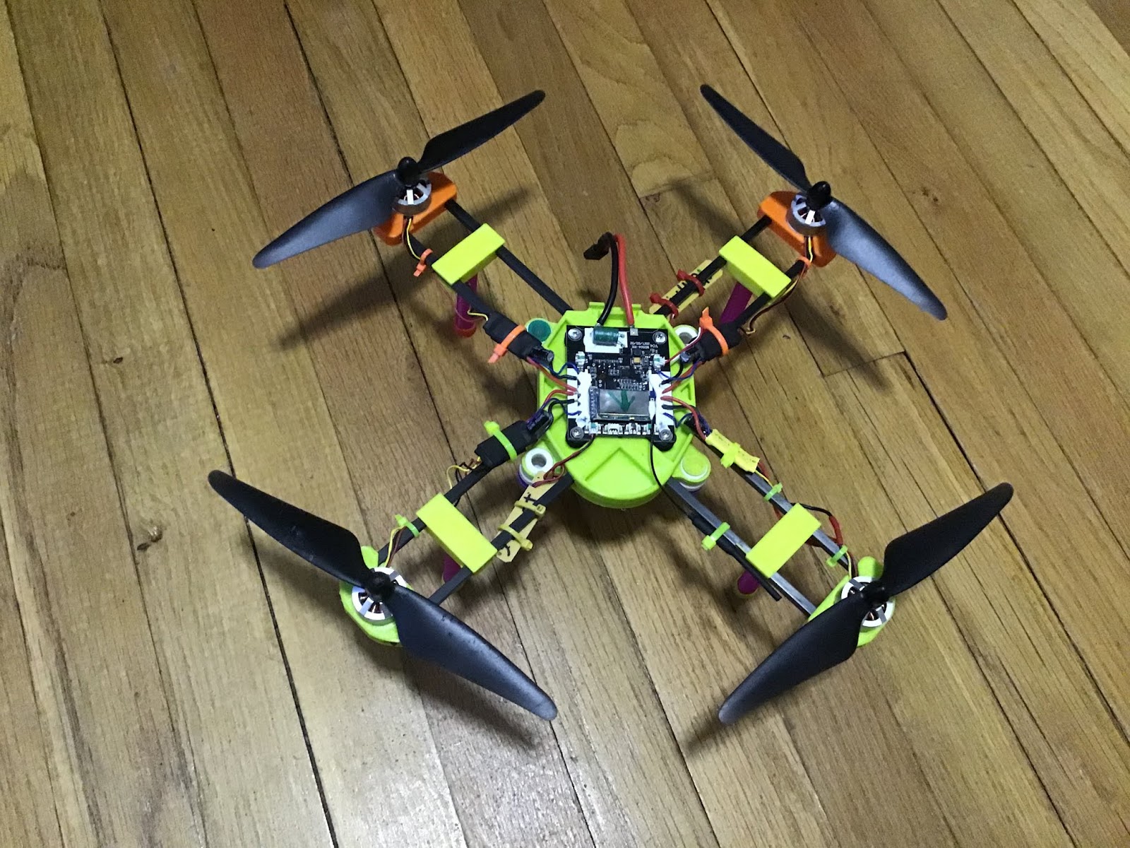
The FrankenBug is a Bugs 3 quadcopter where the electronics have been transplanted to a 3D Printed frame structure. In my case because I crashed it one too many times and the original frame was beyond repair.
This is going to be a write up on the FrankenBug design and basic information on building one. This is very much an on going write up and information will be added as I get time or remember something of importance.
You will need to source -
the files here for printing - FrankenBug
8, square carbon fiber tubes, 5mm x 145mm (slightly smaller or larger should be fine) and generally can be found on Ebay and other retailers of these types of products.
16 small screws (M2- 5 to 8mm long or some pointed style will work)
Anti Vibration balls/balloons made for gimbals to hang the battery/can mount
Zip ties
You will also be better off if you have the ability to print flexible filaments for the leg mounts, though it's not 100% needed, it makes for a better and easier fit and build as well as adds some shock absorption to landings.
Printing-
All Parts should be printed in HT-PLA and annealed or PETG or ABS with the exception of the leg mounts and feet which are better off in TPU/TPEE or other flexible material.
Need to print, 1 body, 4 motor mounts, 4 Leg mounts (TPU/Flexible preferred), 4 legfoot, (TPU/Flexible preferred), 4 legs, as well as one Battery/cam mount. Optional - TPU Cam Pad which just helps keep the camera from sliding around easily.
* Removing supports from the inside of the arm holes in the main body can be a real PAIN so I HIGHLY recommend using Ideamaker, (or S3D if you own it) for a slicer and adding just one line of supports down the middle.
Building -
Basically you just slip the parts together, slap the bugs electronics on top and you're good to go.
I love my aluminum 2020 framed 3D printer. But one thing I noticed rather early on was the bed bearings needed constant attention. There was always something getting on the rods or bearing and the grease or oil was regularly needing reapplying which involves basically tearing the whole lower end of the printer apart. That and the cheap LMU bearings running on the 8mm rods was usually rather sloppy and inaccurate, oh, and very loud! I came up with this method of replacing them with wheels and Openbuild's 2020 V Groove extrusions for a MUCH smoother and quieter operation. Been over 6 months now and it's been about the most reliable part of the printer since.
This isn't complicated, but not exactly easy either, I'm guessing people will likely come up with slight improvements or easier methods of installing. If you do, please share! this is all part of the awesomeness of the 3D Printing community!
Purchased Parts-
2 - 2020 V groove extrusions (length is going to depend on you printer and such but it needs to go at least the length of the frame and I recommend getting a few extra mm's front and back. )
8 - V groove mini wheels (Openbuilds, yes, mini wheels, not the standard larger V groove wheels!)
8 - M5 bolts (25mm long at least) and lock nuts (Openbuild supply the lock nuts with the wheels generally. use the lock nuts, please don't use regular nuts as you'll likely regret it... )
8 - 2020 extrusion mounting 90º angle brackets
16 - M5 Tee nuts
16 - M5 8mm long screws
** one aluminum bed platform if you don't already have one (don't reccomend doing this with an acrylic or other plastic based bed)
Printed parts-
4 - Wheel mounts
2 - turn buckles (2 left thread, 2 right thread 2 centers)
Optional - Will align the belt path for much smoother, more accurate and just all around better operation
Bed carriage mount
Y/Bed idler wheel mount
Y motor mount
Tools -
5mm drill bit (and drill obviously)
Allen/Hex tools for screws (sizes very depending on screw/bolt brands)
Open end, box, socket or adjustable wrench to fit the M5 lock nuts (generally a 8mm socket/wrench)
Calipers
First off print up the 4 wheel mounts, and also the turn buckle parts. Do to all the threading I highly recommend taking the extra time and printing these in a higher, well smaller, layer height for better accuracy and fit. At the standard 0.2 height it's a bit rough I've found to work smoothly, 0.16 or lower seems to work well for me.
Test the threading on the turn buckles, screw them all together and make sure they run smoothly, just working them in and out a bunch helps usually, (also found a bit of rubbing alcohol seems to smooth them out easier if you used PLA)
Locate the holes you want to use in the aluminum bed plate and drill out to fit the M5 screws/bolts, they need to slide through, but preferably not be too sloppy.
Assemble the mini wheels, (make sure you put the washer in-between the 2 bearings, made the mistake of forgetting a couple myself and it makes them useless!! DUH!)
Now assemble the wheel and wheel blocks. Slide the mini wheel onto the M5 bolt, then a washer, (supplied with wheels usually) and screw it into the wheel block. The block is threaded, tighten the bolt until the wheels rolls smoothly still but has no wiggle or play, give it an extra 1/4-1/2 turn but don't over tighten!!! If you strip the threading, you've over tightened. Do all four blocks installing two wheels per block.
Slide block and wheel assembly onto the bed plate through the holes you drilled out. install the lock nuts onto the bolts and tighten by turning the nut while holding the bolt in place, remember the blocks are threaded and turning the bolt will increase the tension on the bearing. Tighten these good but again, don't over tighten. You want the wheel and blocks to be firmly mounted, but not to crush the printed mounts. Install all four wheel/block assemblies.
Now take the two 2020 V-Groove extrusions and set the bed on top of them, push out on the 2020 extrusions till the come in contact with the wheels. Now assemble the turn buckle units with a left, right and center piece. slide the turn buckle unit in-between the 2020 extrusions and, while aligning the tabs into the 2020 grooves, snug up the turn buckle to the extrusions. Do your best to keep both sides equal in length.
Slide the bed to the approximate center of the 2020 extrusions, and making sure they are generally square and equal in placement, keep tightening the turn buckles a small bit at a time doing both equally. Make sure the wheels are in the V groove of the 2020. Get the 2 extrusions and the bed assembly loosely setup so the wheels are rolling in the v grooves. **The bed assembly only sits 1mm above the extrusions, make sure everything is clear and set. If it is riding too low you may need to add an extra washer between the wheel and the blocks to compensate for printed layer height differences of your printer. **
Take the bed and roll it back and forth on the extrusions. "feel" the movement, you can tell if one side is too tight or too loose. Get as good as you can by feel, then take the calipers and measure the distance between the extrusions on both ends. Adjust the turnbuckles so both sides are as exact to each other as possible and the bed is riding smoothly in the grooves but not so loose it had wobble or play.
Once you have the 2 extrusions set and have the bed rolling smoothly, and evenly, now just pick it up and place on you printer frame in place of the old rods and bearings. Use the 8 angle brackets along with the screws and tnuts and mount the assembly to the printer frame. once the brackets are locked down you can remove the turn buckles and install the belt. done, enjoy the smoother operation of your printer.
If you have used the new Cura version you'll probably have noticed it a nice simple interface, but, it is about the longest running time to load of just about any program on you computer. It just takes for........ever. I've discovered though that the long load time is just it starting up and loading a bunch of files and profiles for printers you likely aren't using. This video is a very simple way to delete these files so at start up Cura doesn't waste time loading stuff you don't need.
YES YOU STILL NEED TO DO A FINAL TIGHTEN WHILE HEATED AT THE END...
OK, the general rule is if changing a nozzle or heat break tube that you need to fit it while the whole unit it hot. And, in truth is still going to give you the most reliable connection to prevent slipping or leaking of molten plastic popping out between the nozzle and heat block, or out the top between the heat break tube and the heat block. But, a good tight seal can reliably done while cold if you take the right steps. These step can also be applied in a hot assembling to prevent snapping the heat break.
- First off though, you need to take a few precautions. Mostly the whole thing needs to be clean and free of any material. If a new install/build, not an issue but if rebuilding you need to do a cold pull, then inspect and remove anything plastic material left behind after taking it apart.
Once everything is clean, you'll need just a couple tools, a socket is best but a wrench that fits the nozzle will work. and a wrench to fit the heat block. make sure not to bind, pinch or otherwise damage any wires coming from the heating element and sensor, or damage the items themselves!
Now the steps are easy and will work reliably if done in the correct order.
Install and tighten the nozzle to the heat block, make sure it is seated but you don't need to crank it down. (note there are a few hot ends that want a small gap between the heat block and the nozzle, make sure to check with your manufacturer)
Install and hand tighten the heat tube down to the nozzle. just a snug hand tight.
Back off the nozzle a full 1/2 turn.
Hand tighten the heat break tube down to the nozzle again. Just a snug hand tight.
Now you can install the hot end if you can get to it on the machine, or if not, heat up lying on a heat safe item (Boro glass bed or alum is fine, things like Build tak and such you'll need to protect.)
Now use wrenches on heat block and nozzle and tighten up nice and tight. Obviously being careful not to over tighten and strip the threads.
You may not get back the full 1/2 turn, which should be OK. If there is an excessive gap then loosen the nozzle, back off the heat break tube a 1/4 turn and install/tighten nozzle again.
** You still need to heat and tighten once installed, but should be just snugging it up at this point not trying to fiddle and assemble steaming hot parts**
If you follow these simple steps. you should have no issues ever again with leaking or loosening hot ends.
(Original post from the 3D Printing Experience blog)
Updating info Nov 5th 2017- updating to match latest marlin firmware and to straighten out some of my image rotating which confused some people with orientation. Also to add a few extra bits and info.
If your printer is like mine you may have noticed that prints really aren't centered on the bed of the printer.
Now some printers have adjustable end stops so you can just turn a screw and set where the printer aligns it's self, But most don't have this. And honestly, unless it's really off, or you are going to print something right to the edges of your printers limits, it's not going to matter. But, it bothers me, so I went and learned how to center it. And it's not really all that hard to do. It took me a few days of reading and research to figure it out, and once I did I found it takes very little time to actually center it. So I wrote this so others can do it without having to spend the time figuring it all out.
Now you will need to be at least basically familiar with Marlin firmware and using Arduino or other software but it's not all that hard to figure out.
First step is to make sure your printer is all leveled and set correctly. It's best with this to use PLA, on a taped bed so you can mark it all up. you can just print what ever and take measurements from the edges if you don't want to use a marker on your bed, but this makes it so much easier.
Tape up you bed and move your print head to extremes, Mark the nozzle location as it often time will hit a carriage before it gets to the end of the printers bed
Draw Straight Lines down the edge of the bed where the nozzle actually stops
draw lines from corner to corner to create an X at the center point of the printable area.
Also if you write where your end stops are it will keep you from getting it spun around after printing and you go and take the glass (or what ever you are using) off.
Now download the centering target file, and slice it.
Best use is if you can print at your highest resolution your printer can do and not use any rift or brim if possible. This will allow you to see the marks on the bed through the print.
VERY IMPORTANT - Now make sure you right click on the target and select "center on platform" (this is with Cura, others may have a different command to make the target centered Make sure you use it)
save the Gcode and print it out. After printed take a look at where it lands on the bed. the lines are 5mm space. my X lands right in the corner of the 1st 5mm box, actually just inside, right at the corner. So I'm gunna just say -4.5mm for both X and Y in this case
Now that you have measurements, you can open up your Marlin firmware file and select the "Configuration.h" tab ..
Scroll down to the bottom of the "Z probe Settings"("End Stop Setting" in older version of marlin)
These are the spots where you will enter the measurement you got from the print.
Adding a negative number shifts the bed toward the end stop, (the print away from the end stop) adding a positive number can't be done. Why? because that would make you buildable area out beyond your end stops, which it just can't do, cuz, you know,.. it'll hit the end stop.
Enter your measurements you got off the print, compile and upload to the printer. you should be set now and all your prints should be close to center on the bed.
And print the target again to check and make sure you did it correctly...
All centered!
Now you're prints will be properly centered on the bed from now on :)
(Orginal post from the 3D Printing Experience blog)
OK, if you have been 3D printing for more than a day you've heard the term "leveling you bed" it's not so much actually getting the bed level as it is getting the bed parallel to the plane of the extruder's movements. Level is very important so the first few layers adhere the the bed as well as having them being an equal thickness.
But, this isn't about leveling your bed. This is about how "Square" your frame structure of the printer is. Square is all the axises being 90º from each other, which though not as important to getting the first layer to adhere, but just, if not more important to getting items to print properly, especially if you are trying to print mechanical item that need to fit together and have reasonably tight tolerances. If you're getting prints that are leaning, or just don't fit right, it's likely you may have the frame out of square. Below is an image of the 3 main issues of out of square frame even though the nozzle is leveled with the bed.
results of out of square frame.
(note, Z axis can be out front to back as well as the side lean displayed)
Mostly applies to Prusa i3's and such with moving Y plane bed.
Though the above image it's very visible because I exaggerated the issues, it may be much more slight in your printer to the point it's hard to actually see, but can give problems when printing fitted parts that need to align and work together. I have designed a simple triangle thingie that you can print to check your printer for square. Now you can print any old box, or what ever as long as the bottom, one side and front or rear has a flat straight plane, I just personally like the triangle thingie as I think it looks cool!
Now print it (or what ever) out. Once printed, take a square and check just how well your printer is doing. Honestly, its best if possible to leave the item on the bed. that way it's easier to tell in which direction/what side is out so you can fix or adjust it.
print the little triangle thingie- leave on bed if possible
X to Z axis, lean side to side and tilt front to back.
X to Y axis
Now a "speed square" will work, but the combo-slide square work best in this application as it allows you to lift the bottom edge just a tad to clear any brim or border you may use to adhere the print to the bed.
notice I lifted the edge of the rule to avoid false reading from brim
After checking if you find something out of square you'll need to adjust it. It's going to be widely different depending on printer model and style so I won't get into that whole thing, but you can consult your manufacturer or hit up many of the groups and forums for your particular model.
But, once you have checked and fixed any issues with your printer being out of square then you will notice not only mechanical parts fit better but also organic prints should improve in visual quality.